- Note:
- This guide assumes you are using the mTouch Evaluation kit as your hardware. For details on where to begin when implementing the mTouch framework on a custom hardware design, use this guide.
Congratulations for the purchase of your new mTouch CVD Evaluation Kit.
Although the kit will run right out of the box, this document will walk you through the setup process to quickly configure the kit. Should you need any custom configuration, this will get you up and running.
The kit comes pre-programmed and set to operate in the configuration listed below. If you need to alter any of the parameters, then a new hex file will need to be generated and the main board will need to be reprogrammed with the new firmware. MPLAB IDE will then be required as well as a compatible C compiler.
Hardware Layouts / Configurations:
Each of the board versions listed below has a matching demo project provided in: Your MLA Directory/mTouchCapDemos/PIC16F_CVD_Demos
- 02-02091-R3 :: CVD Eval Board
- 233-04-2028 Rev A :: CVD Eval Board (Use 02-02091-R3 project)
- 02-02091-R2 :: CSM-CVD Eval Board
- 02-02091-R1 :: CSM-CVD Eval Board (Use 02-02091-R2 project)
- 233-04-1008 Rev F :: CSM Eval Board
- 02-02091-RA :: CSM Eval Board
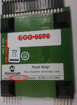
Look on the sticker on the back of the evaluation board to match the project's folder name.
Communicating with the mTouch GUI:
The demo hex files and projects for the evaluation boards are preconfigured to work with the mTouch Two-Way GUI out-of-the box. The default PICKit Serial Analyzer firmware will need to be updated to the latest version. The PICKit Serial Loader utility has been provided to make this easy. You can find it here: Your MLA Directory/mTouchCapDemos/Utilities/PIC12F PIC16F Utilities/PICKit Serial Loader
You must load the PKS-0307-WITHBOOT-0103.HEX when requested by the loader utility. See this guide.
Once this is done, power the mTouch evaluation board externally (through any source other than the PKSA header), connect the PKSA to the board, and start the mTouch GUI.
Changing the Number of Sensors:
If you need the stack to manage more or less than the default number, all you need to do is update the constant MTOUCH_NUMBER_SENSORS to any other value from 1 to 15. This constant can be found in the mTouch_config.h file.
Assigning Sensor Indexes to the Correct A/D Channels
Depending on how the daughter board is connected to the main board, the sensors may be connected to different A/D inputs on the PIC microcontroller. In the mTouch framework, sensors can be mapped to a specific index in the application. Go to mTouch_config.h and look for the section with the definitions shown below, and map the sensor indexes on the left side to the correct A/D channels for your setup.
   #define MTOUCH_SENSOR0             AN0
   #define MTOUCH_SENSOR1             AN1
   #define MTOUCH_SENSOR2             AN2
   #define MTOUCH_SENSOR3             AN3
   #define MTOUCH_SENSOR4             AN4
   #define MTOUCH_SENSOR5             AN5
   #define MTOUCH_SENSOR6             AN6
   #define MTOUCH_SENSOR7             AN7
   #define MTOUCH_SENSOR8             AN8
   #define MTOUCH_SENSOR9             AN9
   #define MTOUCH_SENSOR10            AN10
   #define MTOUCH_SENSOR11            AN11
   #define MTOUCH_SENSOR12            AN12
   #define MTOUCH_SENSOR13            AN13
Changing the Number of Samples per Scan
The number of samples taken in an application will be based on a trade-off between sensitivity and response time. The more samples taken, the better the signal-to-noise ratio of the system, but the slower its response to a finger. Typical response times are less than 100ms to eliminate delay that is visible to the human eye. If a specific response time is required, example equations are provided in the configuration file to show how to calculate the rate that will be chosen based on this value.
Adjusting the Sensor Threshold Values
Your mTouch evaluation kit comes already preconfigured with the sensor threshold values for the 8-button daughter board. If different sensitivities are needed, go to the mTouch_config.h file, locate the section with the definitions shown below, and set the new values. A general rule of thumb to finding and setting correct values is to determine the range of shift for the sensor (min and max shift) and set the threshold to about 75% of the range. The following formula can be used:
![\[ Threshold_{Press} = min + 0.75 (max - min) \]](form_2.png)
   #define THRESHOLD_PRESS_SENSOR0         65
   #define THRESHOLD_PRESS_SENSOR1         65
   #define THRESHOLD_PRESS_SENSOR2         65
   #define THRESHOLD_PRESS_SENSOR3         65
   #define THRESHOLD_PRESS_SENSOR4         65
   #define THRESHOLD_PRESS_SENSOR5         65
   #define THRESHOLD_PRESS_SENSOR6         65
Configuration and Application API Hooks
See the basic sensor configuration guide and the feature-specific help section.