Introduction
The PICKit Serial Analyzer (PKSA) is an easy way to connect the UART of your PIC® microcontroller to your PC. All of the required steps are handled by the PICKit Serial Loader Utility provided with the framework in the 'Utilities' folder of the demos.
Your MLA Directory/mTouchCapDemos/Utilities/PIC12F PIC16F Utilities/PICKit Serial Loader
There are two different ways the PKSA can be used:
- UART-to-USB converter :: UART_USB_PICKitSerial_V1.40.hex :: PKSA behaves as a COM port when connected to the PC.
- Default PKSA Behavior :: PKS-0307-WITHBOOT-0103.HEX :: PKSA behaves as an HID device that is manipulated through a DLL.
An update to the default PKSA hex file is provided to add support for the RS-232 'break' character. This is required for communicating with the mTouch two-way GUI.
Changing the PICKit Serial Analyzer's Hex File
-
Press the button on the PICKit Serial Analyzer when connecting to PC's USB to enter
Bootloader Mode.
(The 'Target' and 'Busy' LEDs should be flashing quickly.) - Open the PICKit Serial Loader Utility provided by the framework in the Utilities folder of the demos.
- Follow the on-screen instructions to load the new hex file. Hex files and drivers are provided in the same folder as the loader utility. Make sure to select correct hex file depending on the desired behavior (UART-to-USB COM port / Updated Default PKSA).
Using your PICKit Serial as a UART-to-USB Converter
-
Unplug and replug the PKSA. Press and hold the black PKSA button to toggle the on-board 5V power supply.
- Warning: There is no protection provided on this power supply. Maximum current is 20mA.
-
LED Status Legend:
- Target LED On: Transmission in progress
- Busy LED On: Reception was successful
Using your PICKit Serial with the default PKSA firmware
- Power your mTouch board and connect the PKSA.
- Open the mTouch Two-Way GUI. The program will begin communicating or will provide error messages with suggestions for resolve any issues.
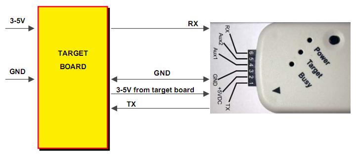
Example schematic connecting the PKSA with an external power supply
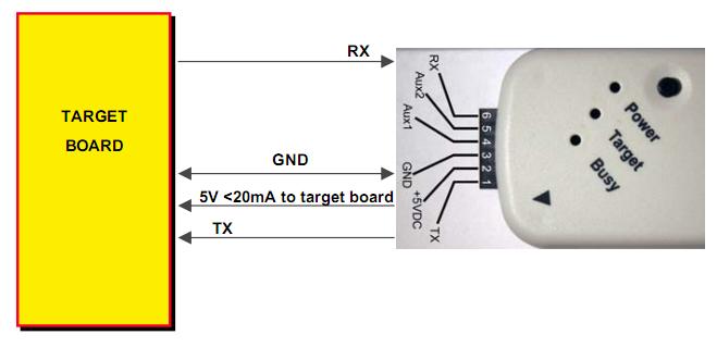
Example schematic of PKSA supplying power to the board
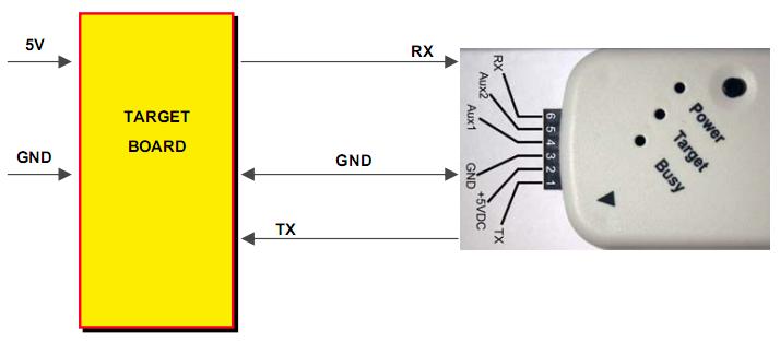
Example schematic of connecting PKSA with an external 5V power supply. Notice - no VDD connection required.
Maximum Speed: 115.2 kbps
Voltage Level: Depends on the voltage applied to pin #2. Valid range is from 3-5V.
Optional 5V (<20mA) power supply from the PICKit Serial Analyzer.
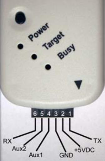
PICKit Serial Analyzer Pin Configuration
- The PC's TX line. The PIC's RX line. (Marked with an arrow)
- VDD : 3-5V
- VSS
- Aux1 : not used in RS232 configuration
- Aux2 : not used in RS232 configuration
- The PC's RX line. The PIC's TX line.