Getting Started: Running the “Device
– PHDC – Basic Demo” demo
Configuration
1: PICDEM FS USB
Configuration
2: PIC18F87J50 PIM
Configuration
4: Low Pin Count USB Development Kit
Configuration
5: PIC24F Starter Kit 1
Configuration
6: PIC18F46J50 Full Speed USB Demo Board
Configuration
7: PIC32 USB Starter Board
Configuration
8: PIC18F Starter Kit
Configuration
1: PICDEM FS USB
Configuration
2: PIC18F87J50 PIM
Configuration
4: Low Pin Count USB Development Kit
Configuration
5: PIC24F Starter Kit 1
Configuration
6: PIC18F46J50 Full Speed USB Demo Board
Configuration
7: PIC32 USB Starter Board
Configuration
8: PIC18F Starter Kit
Required Hardware:
To run this project, you will need one of the
following sets of hardware:
Configuration 1: PICDEM FS USB
PICDEM
FS USB (DM163025)
Configuration 2: PIC18F87J50 PIM
PIC18F87J50
Plug-In-Module (PIM) (MA180021)
Configuration 3: Explorer 16
Explorer
16 (DM240001)
USB
PICtail™ Plus Daughter Card (AC164131)
And one of the following PIMs
PIC24FJ256GB110
Plug-In-Module (PIM) (MA240014)
PIC32MX
USB Plug-In-Module (PIM) (MA320002)
Configuration 4: Low Pin Count USB Development Kit
Low
Pin Count USB Development Kit with PICKit 2 Debugger/Programmer (DV164126)
or without Debugger/Programmer (DM164127)
Configuration 5: PIC24F Starter Kit 1
PIC24F
Starter Kit 1 (DM240011)
Configuration 6: PIC18F46J50 Full Speed USB Demo Board
PIC18F46J50
Full Speed USB Demo Board (MA180024)
Configuration 7: PIC32 USB Starter Board
PIC32 USB Starter Board (DM320003)
Configuration 8: PIC18F Starter Kit
PIC18F Starter Kit (DM180021)
Configuring the Hardware:
This
section describes how to set up the various configurations of hardware to run
this demo.
Configuration 1: PICDEM FS USB
Configuration 2: PIC18F87J50 PIM
Configuration 4: Low Pin Count USB Development
Kit
Configuration 5: PIC24F Starter Kit 1
Configuration 6: PIC18F46J50 Full Speed USB Demo Board
Configuration 7: PIC32 USB Starter Kit
Configuration
8: PIC18F Starter Kit
Configuration 1: PICDEM FS USB
1)
If using the PICDEM FS USB Demo Board, no hardware related configuration or
jumper setting changes should be necessary.
The demo board need only be programmed with appropriate firmware.
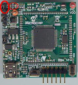
Configuration 2: PIC18F87J50 PIM
1)
Short JP4 on the PIC18F87J50 PIM. This
allows the demo board to be powered through bus power.
2)
Short JP1 such that the “R” and “U” options are shorted.
3) Short JP5 on
PIC18F87J50 PIM. This connects the LEDs to RE0 and RE1 pins of the
Microcontroller.
Configuration 3: Explorer 16
1)
Before attaching the PIM to the Explorer 16 board, insure that the processor
selector switch (S2) is in the “PIM” position as seen in the image below.
2)
Short the J7 jumper to the “PIC24” setting
3)
Before connecting the PIM to the Explorer 16 board, remove all attached cables
from both boards. Connect the PIM to the
Explorer 16 board. Be careful when
connecting the boards to insure that no pins are bent or damaged during the
process. Also insure that the PIM is not
shifted in any direction and that all of the headers are properly aligned.
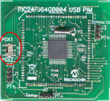
3a)
If using the PIC24FJ64GB004 PIM, please insure that the programming port
switch is switched in the PGX1 direction.
4) On the USB PICTail Plus board, short jumper
JP1. Remove all other shorts on the
board.
5) Connect the USB PICTail Plus board to either
of the female PICTail Plus connectors or on the card edge connector (J9) at the
edge of the Explorer 16 board.
Note: When using the HID bootloader
for PIC32, it is important to modify the procdefs.ld file to relocate the
sections of code that will hold the bootloader and those sections that will
hold the user application. Example
modified procdefs.ld files have been provided with each project. This file is currently named
“Procdefs.ld.boot”. When using the
example project with the bootloader it is required to remove the “.boot”
section of the file. This will allow MPLAB
to use this file instead of the default linker file. Once the linker file is renamed, however, the
project will no longer work without the bootloader. Please rename the file in order to get the
project working again with PIC32.
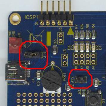
Configuration 4: Low Pin Count USB Development Kit
1) Short pins 2 and 3 of J14. Make sure J12 is left open.
Configuration 5: PIC24F Starter Kit 1
The PIC24F Starter Kit does not require any hardware setup
to run this demo. This demo does,
however, require the user to change the default selected device in the project
before compiling the demo.
1) Open the associated project file
for C30
2) In MPLAB Select
“Configure->Select Device”
3) In the device list box in the top
left corner of that window, select “PIC24FJ256GB106”
Configuration 6: PIC18F46J50 Full Speed USB Demo Board
1) Short JP3 to allow the board to
be powered from the USB.
.jpg)
Configuration 7: PIC32 USB Starter Board
No specific hardware configuration is required for this
demo. Use the OTG cable provided with the starter kit to connect OTG connector
J5 (on the bottom side of the starter kit) to the PC.

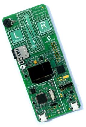
Configuration 8: PIC18F Starter Kit
No specific hardware configuration is required for this
demo.
To
run this project, you will need to load the corresponding firmware into the
devices. There are two methods available
for loading the demos: Precompiled demos and source code projects.
Precompiled
Demos are available in the “<Install Directory>\USB – Precompiled Demos”
folders. Each demo should be prefaced
with the hardware platform it is compiled for.
Select the file that matches the hardware that you have and the demo
that you want to run. For more
information about how to load a precompiled project, please see the “Getting
Started – Loading a precompiled demo” guide.
The
source code for this demo is available in the “<Install Directory\USB Device
– PHDC – Basic Demo” directory. In this
directory you will find all of the user level source and header files as well
as project and workspace files for each of the hardware platforms. Find the project (*.mcp) or workspace (*.mcw)
file that corresponds to the hardware platform you wish to test. Compile and program the demo code into the
hardware platform. For more help on how
to compile and program projects, please refer to the MPLAB® IDE help available
through the help menu of MPLAB IDE (Help->Topics…->MPLAB IDE).
Please
note that when using either the C30 or C32 demo projects you will be required
to select the correct processor for the demo board.
1) Open the associated project file
2) In MPLAB Select
“Configure->Select Device”
3) In the device list box in the top
left corner of that window, select the desired device.
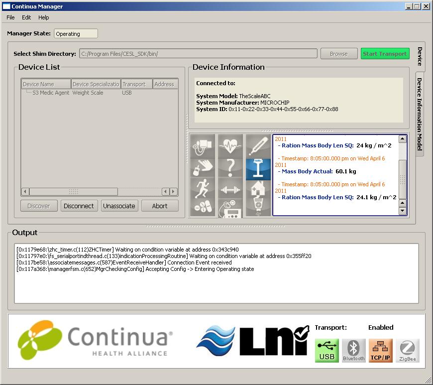
The user needs to install the Continua Manager GUI in
order to see the measured data which would be transmitted from the device. To
obtain the Continua manager GUI one needs to be a member of the Continua org.
In order to run this demo first compile and program the target device. Attach the device to the host. If the host is a PC and this is the first
time you have plugged this device into the computer then you may be asked for a
.inf file. The .inf file is provided by
Continua org. The demo user needs to be a member of the Continua org to access
the CESL software and the Continua Agent USB driver files provided by them.

Select
the “Install from a list or specific location (Advanced)” option. Point to the
“<Install Directory>\USB\Device - PHDC - Weighing Scale\Driver and INF”
directory.

Once the device is successfully installed, open up
the Continua Manager GUI. On the GUI the “Start Transport” button has to be
pressed to connect with the device. The device now will be connected to
manager.
It needs two push buttons on the device board to
showcase the PHDC application. The PHDC application provided emulates a weigh
scale. Each press on a push button performs specific tasks. One of the push
button toggles between “Unassociated” and “Operating” state. The other one on
assertion sends the measured data to the Continua Manager. The Weigh Scale
measurement will be sent only when both Manager and agent are in Operating
States.
In some of the Microchip USB demo boards there is
only one Pushbutton. In those demo boards with only one pushbutton the Agent
(PHDC Device) Connects to the Manager when the pushbutton is pressed for the
First time. When the pushbutton is pressed for the second time the device sends
measured data to the device. When the pushbutton is pressed for the third time
the device Disconnects from the Manager.
Examples for demo boards with only one pushbutton are PIC18F46J50 PIM,
PIC18F46J50 PIM, PIC18F87J50 PIM, PIC18F Starter Kit and Low Pin Count USB
Development Kit.
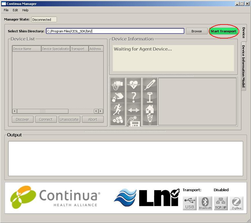 E
E
Click on Start Transport Button
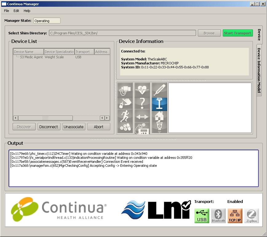
Press Push Button on the device to
enter in Operating state. The Continua Manager indicates that it is in
Press Pushbutton on the device to
Send Measured Data to the Manager. The
continua Manager displays the received data from the Agent (PHDC device).
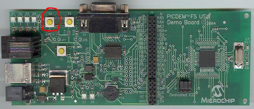
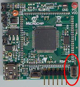
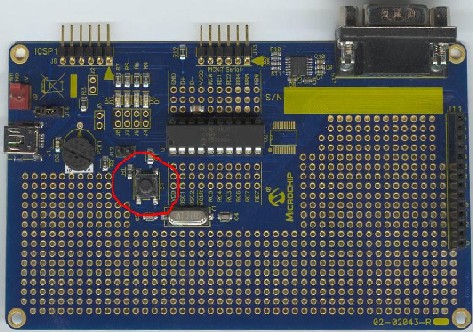
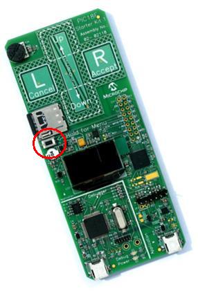
Push Button
PICDEM
FS USB:
PIC18F87J50
PIM:
Explorer
16:
Low pin count USB development kit:
PIC24F Starter Kit 1:
The PIC24F
Starter Kit 1 does not implement the pushbutton for these demos. This functionality is not present in this
demo.
PIC18F46J50 Full Speed USB Demo Board:
.jpg)
PIC32 USB Starter Kit

PIC18 Starter Kit
Trademarks:
The Microchip name and logo, the Microchip logo,
MPLAB, and PIC are registered trademarks of Microchip Technology Incorporated
in the
PICDEM and PICTail are registered trademarks of
Microchip Technology Incorporated in the
Microsoft, Windows, and Windows Vista are either
registered trademarks or trademarks of Microsoft Corporation in the


.JPG)
.JPG)
.JPG)
.JPG)