Getting Started: Running the “Device – CCID – Smart Card Reader” demo
Configuration
1: PIC18F87J50 PIM + HPC Explorer
Configuration
2: PIC18F46J50 Full Speed USB Demo Board + HPC Explorer
Configuration
4: Low Pin Count USB Development Kit
Configuration
5: PICDEM FS USB
Configuration
1: PIC18F87J50 PIM + HPC Explorer
Configuration
2: PIC18F46J50 Full Speed USB Demo Board + HPC Explorer
Configuration
4: Low Pin Count USB Development Kit
Configuration
5: PICDEM FS USB
Required Hardware:
To run this project, you will need one of the
following sets of hardware:
Configuration 1: PIC18F87J50 PIM + HPC Explorer
PIC18F87J50
Plug-In-Module (PIM) (MA180021)
PICDEM HPC Explorer Board (DM183022)
SC (Smart/Sim Card) PICTail Board
Configuration
2: PIC18F46J50 Full Speed USB Demo Board + HPC Explorer
PIC18F46J50
Full Speed USB Demo Board (MA180024)
PICDEM HPC Explorer Board (DM183022)
Configuration 3: Explorer 16
Explorer
16 (DM240001)
USB PICtail™ Plus Daughter
Card (AC164131)
SC (Smart/Sim Card) PICTail Board
And one of the following PIMs
PIC24FJ256GB110
Plug-In-Module (PIM) (MA240014)
Configuration 4: Low Pin Count USB Development Kit
Low Pin Count USB Development Kit with PICKit 2 Debugger/Programmer (DV164126) or without Debugger/Programmer (DM164127).
SC (Smart/Sim Card) PICTail Board
Configuration 5: PICDEM FS USB
PICDEM
FS USB (DM163025)
SC (Smart/Sim Card) PICTail Board
Configuring the Hardware:
This
section describes how to set up the various configurations of hardware to run
this demo.
Configuration 1: PIC18F87J50 PIM + HPC Explorer
Configuration
2: PIC18F46J50 Full Speed USB Demo Board + HPC Explorer
Configuration 4: Low Pin Count USB Development Kit
Configuration 5: PICDEM FS USB Board
Configuration 1: PIC18F87J50 PIM + HPC Explorer
1)
Before attaching the PIC18F87J50 PIM to the HPC Explorer board, insure that the
processor selector switch (S3) is in the “ICE” position as seen in the image
below. Failure to do so will result in
difficulties in getting the PIC18F87J50 to sit properly on the HPC
Explorer.
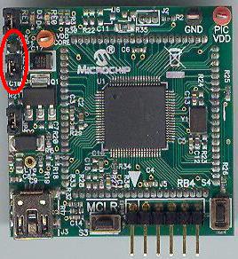
2) Short JP4 on the
PIC18F87J50 PIM. This allows the demo board to be powered through bus power.

3) Short JP1 such that the
“R” and “U” options are shorted.
4)
Before inserting PIC18F87J50/PIC18F46J50 PIM into the HPC Explorer board,
remove all the attached cables from both the boards. Be careful while inserting
the PIM into HPC board. Insure that no pins are bent or damaged during the
process. Also insure that the PIM is not
shifted in any direction and that all of the headers are properly aligned.
5)
Insert the J4 port of SC (Smart/Sim
Card) PICTail Board to the J3
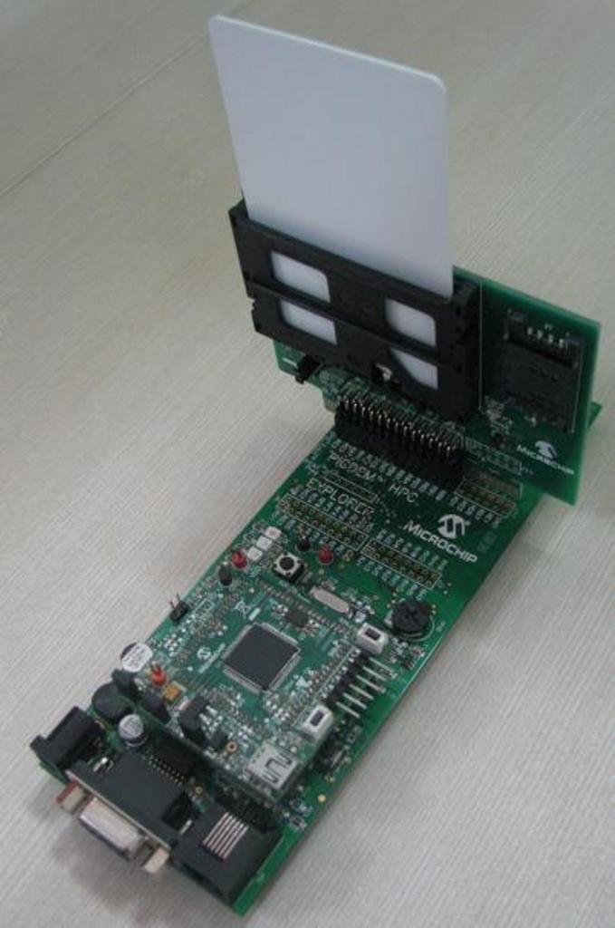
Configuration 2: PIC18F46J50 Full Speed USB Demo Board + HPC Explorer
1)
Before attaching
the PIC18F46J50 PIM to the HPC Explorer board, insure that the processor
selector switch (S3) is in the “ICE” position as seen in the image below. Failure to do so will result in difficulties
in getting the PIC18F46J50 to sit properly on the HPC Explorer.
2)
Short JP3 to allow the
board to be powered from the USB
.jpg)
3)
Before connecting the
PIM to HPC Explorer, remove all attached cables from both boards. Connect the PIM to the
HPC Explorer board. Be careful when connecting the boards to insure that no pins are
bent or damaged during the process. Also insure that the PIM
is not shifted in any direction and that all of the headers are properly
aligned.
4)
Insert the J4 port of SC
(Smart/Sim Card) PICTail
Board to the J3 port of HPC Explorer board. Make sure that the Smart Card
Connector is facing towards the HPC Explorer board. Insert the Smart Card in SC
PICTail Board.
Configuration 3: Explorer 16
1)
Before attaching the PIM to the Explorer 16 board, insure that the processor
selector switch (S2) is in the “PIM” position as seen in the image below.
2)
Short the J7 jumper to the “PIC24” setting
3)
Before connecting the PIM to the Explorer 16 board, remove
all attached cables from both boards. Connect the PIM to the
Explorer 16 board. Be careful when connecting the boards to insure that no pins are
bent or damaged during the process. Also insure that the PIM
is not shifted in any direction and that all of the headers are properly
aligned.
3a) If using the PIC24FJ64GB004
PIM, please insure that the programming port switch is switched in the PGX1
direction.
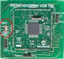
4) On the USB PICTail Plus board, short jumper
JP1. Remove all other shorts
on the board.
5) Connect the USB PICTail Plus board to either of the female PICTail Plus connectors or on the card edge connector (J9) at the edge of the Explorer 16 board.
6)
Short JP1 to
SRC1 (i.e. RD1) or SRC2 (i.e. RB15) based upon the smart card clock pin
configured in the firmware:
If
using PIC24FJ256GB110 PIM short JP1 between CLK and SRC2 (i.e. RB15).
If
using PIC32MX460F512L PIM or PIC32MX795F512L PIM, short JP1 between CLK and
SRC1 (i.e. RD1).
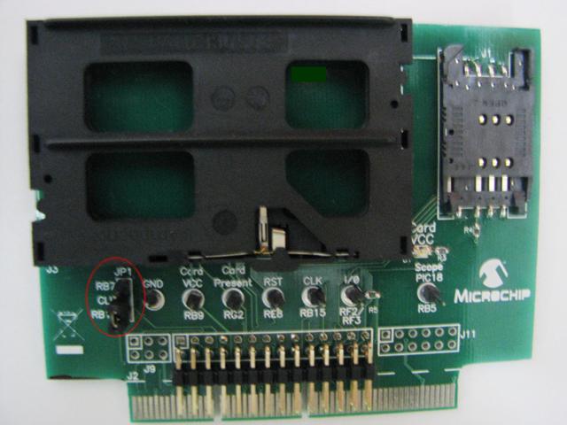
7)
Insert the J2
Configuration 4: Low Pin Count USB Development Kit
1)
Make sure J12 of LPC board is left open. One side of J4 port pins of the SC
(Smart/Sim Card) PICTail
Board match with the J11 port of LPC board. Insert the matching side of J4 port
of SC PICTail board into the J11 port of LPC board.
Make sure that the Smart Card Connector is facing towards the LPC board. Insert
the Smart Card in SC PICTail board.
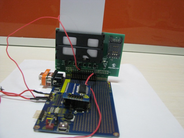
1) Short Tx
& Rx line of the UART at J13 port using a wire and connect it to I/O pin of
SC PICTail board.
2) Connect RB6 (of J13 port) to
“Card Present” signal pin of SC PICTail board.
Configuration 5: PICDEM FS USB
1) The
Jumper JP11 needs to be open in this board. In some revision of the board it
may necessary to cut the PCB track that is shorting the jumper.
2) Insert the J2 port of SC (Smart/Sim Card) PICTail card into J3
port of PICDEM FSUSB board as per the pin configuration. Insert the Smart Card
in SC PICTail board.
To run this project, you will need to load the
corresponding firmware into the devices. There are two methods
available for loading the demos: Precompiled demos and source code projects.
Precompiled Demos are available in the “<Install
Directory>\USB – Precompiled Demos” folders. Each demo should be
prefaced with the hardware platform it is compiled for. Select the file that
matches the hardware that you have and the demo that you want to run. For more information
about how to load a precompiled project, please see the “Getting Started –
Loading a precompiled demo” guide.
The source code for this demo is available in the
“<Install Directory>\Microchip Solutions\USB Device - CCID - Smart Card
Reader” directory. In this directory you
will find all of the user level source and header files as well as project and
workspace files for each of the hardware platforms. Find the project (*.mcp)
or workspace (*.mcw) file that corresponds to the
hardware platform you wish to test.
Compile and program the demo code into the hardware platform. For more help on how to compile and program
projects, please refer to the MPLAB® IDE help available through the help menu
of MPLAB (Help->Topics…->MPLAB IDE).
Please note that when using the C30 demo projects you
will be required to select the correct processor for the demo board.
1) Open the associated project file
2)
In MPLAB Select “Configure->Select Device”
3)
In the device list box in the top left corner of that window, select the
desired device. Build the code & program the selected device.
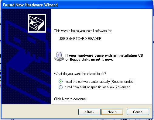
This demo allows the selected hardware platform as a USB CCID
Smart Card Reader to the host. In order to run this demo first compile and
program the target device. Attach the device to the
host. If the host is a Windows PC and this is the first time you have
plugged this device into the computer then you may be prompted with “New
hardware found” wizard.
Click on Next to
continue.
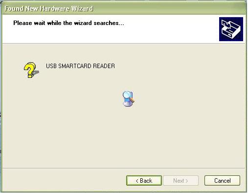
Select “Install the
Software automatically” and click on next.
Click on Next to
continue.
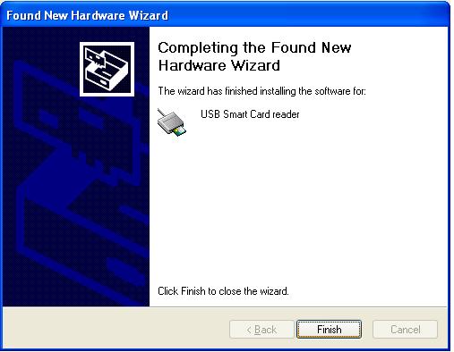
Click on Finish to
complete the installation.
Note:
Microsoft states that Usbccid.sys is compliant with Microsoft Windows
2000, Windows XP, and Microsoft Windows Server 2003 operating systems, and is
available on Windows Update (http://www.microsoft.com/whdc/device/input/smartcard/usb_ccid.mspx). You might need to do a ‘Windows update’ if
you windows computer does not have usbccid driver (or
software required to install a usbccid
driver) currently.
Using jSmartCardExplorer
Download SmartCardExplorer from http://www.primianotucci.com/default.php?view=112. Attach the demo board to the Computer. Ensure that the Smart Card
is inserted on the SC Pictail Card. Launch the jSmartCardExplorer
Application.
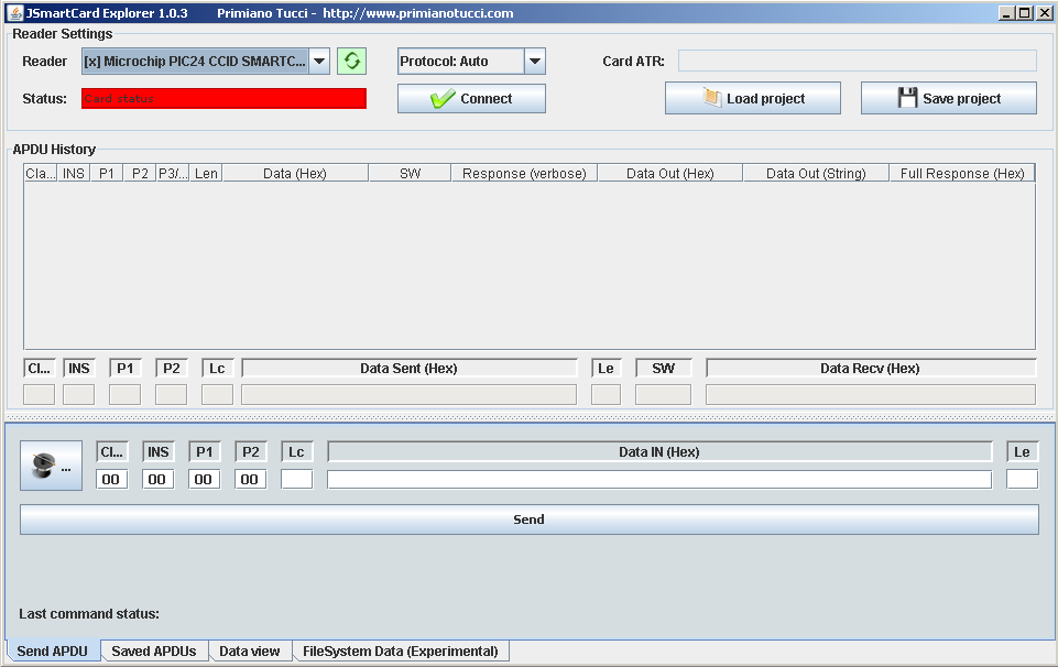
Select
Protocol T=0 or T=1 based on the type of Smart card you insert and click on
Connect Button. If the Smart Card is inserted on the SC Pictail
Card, the ‘Status’ field turns green and the ATR of the Smart Card is displayed on the ‘Card ATR’ field.
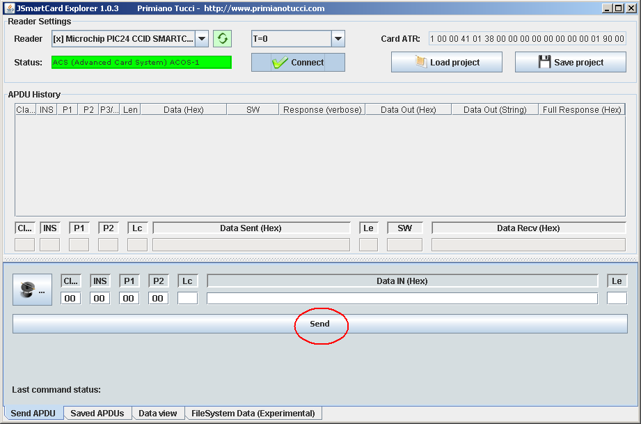
The APDU can be send to the Smart
Card by clicking on the ‘Send’ Button in the Send APDU section. The Command and Data fields need to be filled
before sending an APDU to the Smart Card. Please refer the Smart Card reference
manual from the manufacturer of the Card for the Command list supported by the
Card. The Response from the Smart Card is displayed in the APDU History
Section.
A few sample commands for the ACS ACOS3 card is listed
below.
|
Command |
CLA |
INS |
P1 |
P2 |
LC |
DATA |
LE |
Description |
|
Select
File |
80 |
A4 |
00 |
00 |
02 |
FF00 |
00 |
Selects
File FF00 |
|
Read
Record |
80 |
B2 |
00 |
00 |
00 |
- |
08 |
Reads 8
Bytes from Record No 0 of FF00 file |
Trademarks:
The Microchip name and logo, the Microchip logo,
MPLAB, and PIC are registered trademarks of Microchip Technology Incorporated
in the U.S.A. and other countries.
PICDEM and PICTail are
trademarks of Microchip Technology Incorporated in the U.S.A. and other
countries.
Microsoft, Windows, and Windows Vista are either
registered trademarks or trademarks of Microsoft Corporation in the United
States and/or other countries.
SD is a trademark of the SD Association in the
U.S.A and other countries
.JPG)
.JPG)
.JPG)
.JPG)


