This section describes
how to set up the various configurations of the hardware to run a demo.
Configuration
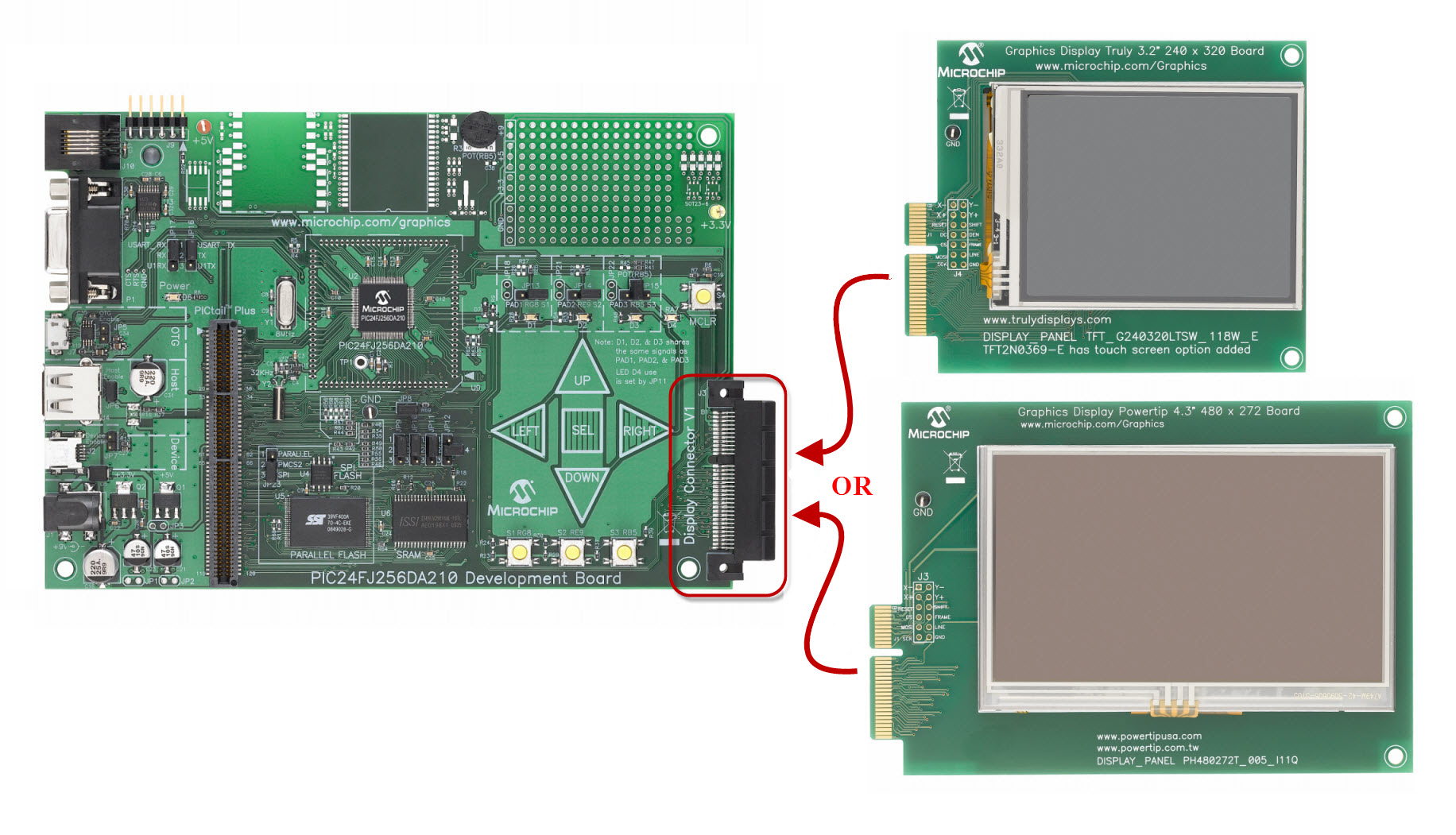
1: PIC24FJ256DA210 Development Board
Configuration
3: Graphics LCD Controller PICtail™ Plus Board with Starter Kits
Configuration
4: Multimedia Expansion Board
Configuration 1: PIC24FJ256DA210 Development Board
1)
Before attaching
the Display Boards to the PIC24FJ256DA210 Development Board, make sure that the
jumpers on the development board are set to the default positions as seen in
the image below. Failure to so will
result in some features and functionalities of the demo to fail.
A.
JP8 – Install
jumper
B.
JP9, JP10, JP11
– Install jumper to pins 1-2
(if using a display with AR1020 support, and AR1020 is selected, then set JP9
and JP10 to pins 2-3)
(if using a display configuration that requires more than 256Kbyte of external
RAM, such as VGA 8bpp, then set JP11 to pins 2-3)
C.
JP12 – Install
jumper to pins 2-4
D. JP13 – Install jumper to pins RG8-S1
E.
JP14 – Install
jumper to pins RE9-S2
F.
JP15 – Install jumper to pins RB5-POT
G. JP16 – Install jumper to TX-USART_TX
H.
JP17 – Install
jumper to RX-USART_RX
I.
JP23 – Install
jumper to PMCS2-SPI (if using parallel flash, then set it to PMCS2-PARALLEL)

2)
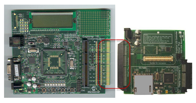
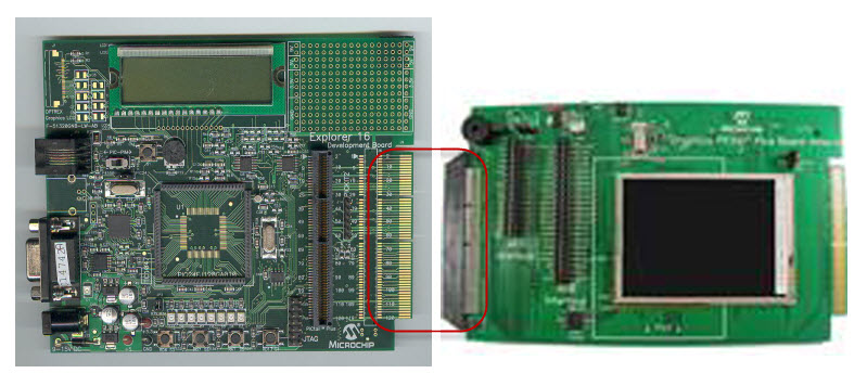
Connect one of the Display Boards to the PIC24FJ256DA210 Development Board
using the Display Connector V1.
Configuration 2: Explorer 16
1)
Before attaching the PIM to the Explorer 16 board, insure that the processor
selector switch (S2) is in the “PIM” position as seen in the image below.
.JPG)
2)
Short the J7 jumper to the “PIC24” setting
.JPG)
3)
Before connecting the PIM to the Explorer 16 board, remove all attached cables
from both boards. Connect the PIM to the
Explorer 16 board. Be careful when
connecting the boards to insure that no pins are bent or damaged during the
process. Also insure that the PIM is not
shifted in any direction and that all of the headers are properly aligned.
4)
An explorer 16 board can be used with 3 different Graphics Picatil
boards. Parts A and B discuss the different setups of the boards:
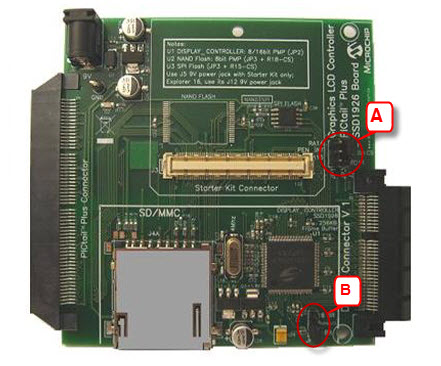
When using the Graphics LCD Controller PICtail™
Plus SSD1926 Board. (GFXv3)
A.
Set the SPI
Flash chip select signal to use RD1 by setting JP3 of the Graphics LCD
Controller PICtail™ Plus SSD1926 Board to RD1-FLASH
CS. Leave JP1 open.
B.
Set up the PMP
interface:
1.
When running the
demo in the 8-bit PMP interface mode set JP2 of the Graphics LCD Controller PICtail™ Plus SSD1926 Board to PARALLEL-8 Bit
2.
When running the
demo in the 16-bit PMP interface mode set JP2 of the Graphics LCD Controller PICtail™ Plus SSD1926 Board to PARALLEL-16 Bit
When using the Graphics LCD Controller PICtail™
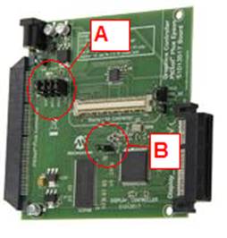
Plus S1D13517 Board. (GFXv3e)
A. Set the SPI Channel used by setting the 4
SPI1 or SPI2 jumpers of the Graphics LCD Controller PICtail™
Plus S1D13517 Board. Leave JP1 open.
B Set up the PMP interface:
1. When running the demo in the 8-bit PMP
interface mode open JP2 of the Graphics LCD Controller
PICtail™ Plus S1D13517 Board
2.
When running the
demo in the 16-bit PMP interface mode close JP2 of the Graphics LCD Controller PICtail™ Plus S1D13517 Board
When using the Low Cost Controllerless
Graphics PICtail™ Plus Board. (LCC)
A.
Set J4 to 1-2
for internal SRAM use or 2-3 for external SRAM use
B.
Set jumpers J6-J19 to (1-2) for 8 (332) bit color
mode or (2-3) for 16-bit (565) color mode
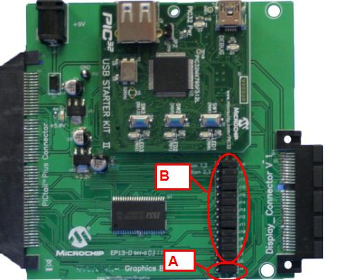
C.
Now the your
graphics PICTail board is properly configured, using
the J9 edge connector of the Explorer 16 board, connect a Graphics LCD
Controller PICtail™ Plus Board.
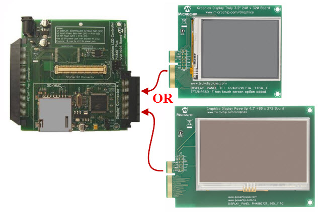
D. Connect one of the 4 Display Boards (QVGAv1, WQVGAv1,
VGAv1, WVGAv1) to
a Graphics PICtail™
Plus Board using the Display Connector V1.
5)
When using the Graphics PICtail Plus
Daughter Board:
Connect the Graphics PICtail
Plus Daughter Board to the Explorer 16 Board using the
J9 edge connector of the Explorer 16 board.
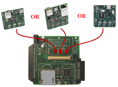
Configuration 3: Graphics LCD Controller PICtail™ Plus Board with Starter Kits
1)
Using the Starter Kit Connector (J3), connect the Starter Kit to a Graphics LCD
Controller PICtail™ Plus Board. There are three boards
available. Step 2 shows how each board should be
configured
2a)
Set up Graphics LCD Controller PICtail™
Plus SSD1926 Board.
A.
Set the SPI
Flash chip select signal to use RD1 by setting JP3 of the Graphics LCD
Controller PICtail™ Plus SSD1926 Board to RD1-FLASH
CS. Leave JP1 open.
B.
Set up the PMP
interface:
i.
When running the
demo in the 8-bit PMP interface mode set JP2 of the Graphics LCD Controller PICtail™ Plus SSD1926 Board to PARALLEL-8 Bit
ii.
When running the
demo in the 16-bit PMP interface mode set JP2 of the Graphics LCD Controller PICtail™ Plus SSD1926 Board to PARALLEL-16 Bit
2b)
Set up Graphics LCD Controller PICtail™
Plus S1D13517 Board.
A. Set the SPI Channel used by setting the 4
SPI1 or SPI2 jumpers of the Graphics LCD Controller PICtail™
Plus S1D13517 Board. Leave JP1 open.
B Set up the PMP interface:
i. When running
the demo in the 8-bit PMP interface mode open JP2 of
the Graphics LCD Controller PICtail™ Plus S1D13517
Board
ii.
When running the
demo in the 16-bit PMP interface mode close JP2 of the Graphics LCD Controller PICtail™ Plus S1D13517 Board
2c) When using the Low Cost Controllerless
Graphics PICtail™ Plus Board. (LCC)
A.
Set J4 to 1-2
for internal SRAM use or 2-3 for external SRAM use
B.
Set jumpers J6-J19 to (1-2) for 8 (332) bit color
mode or (2-3) for 16-bit (565) color mode
3)
Connect one of the 4 Display Boards (QVGAv1, WQVGAv1, VGAv1, WVGAv1) to a Graphics PICtail™ Plus Board
using the Display Connector V1.
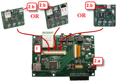
Configuration 4: Multimedia Expansion Board
1) Using the Starter Kit Connector (J3) located on the
underside of the Multimedia Expansion Board, connect one of the Starter Kits to
the Multimedia Expansion Board.
1) Power up the Multimedia Expansion
Board
a. using a 9V power supply using the J1
connector
b. through the USB
connector of the Starter Kit used.