Description:
This was the first version of the board that used the 28 Pin SOIC
version of the PIC. Why is it called version 3 then? I guess that I
just forgot to change the version number when started with the 28 DIP
V3 design and changed it to use the SOIC part. It should have been
called V1, but big deal.
So this version uses the SOIC part. It's a cute little design, except
for two really big problems. One is that the buttons and LEDs are on
opposite sides of the board. You really need them all to be on the same
side. The second problem is that the buttons are really, really tiny.
So tiny that it's hard to push them with your finger, and really hard
to solder them down. So both things got improved with version 4 of the
SOIC design.
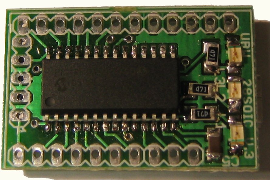
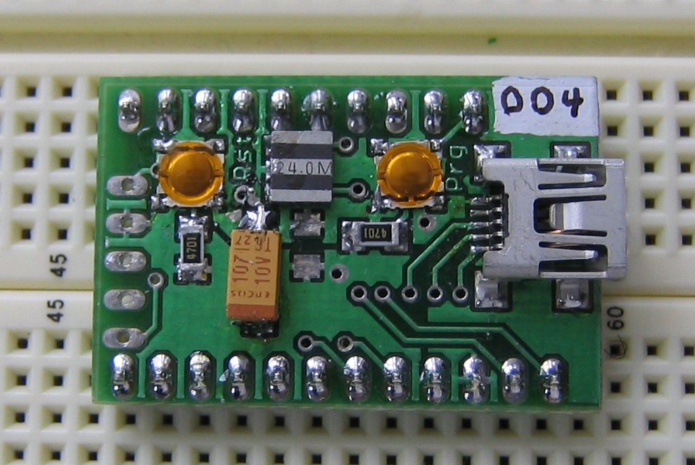
If you build this version, or somehow get a board of this version, you
have to decide where to put the header pins. On the left hand picture
above, you see the 'front' of the board, without any headers attached.
On the right is the 'back' of the board, with headers going down into
the breadboard. You'll have access to either the switches, or the LEDs,
but not both.
You can, however, attached a 90degree header along the side of the
board, (port B side) and then plug the board vertically into the
breadboard. You'll get access to both the swtiches and the LEDs that
way, but you coudn't access all of the I/O lines.
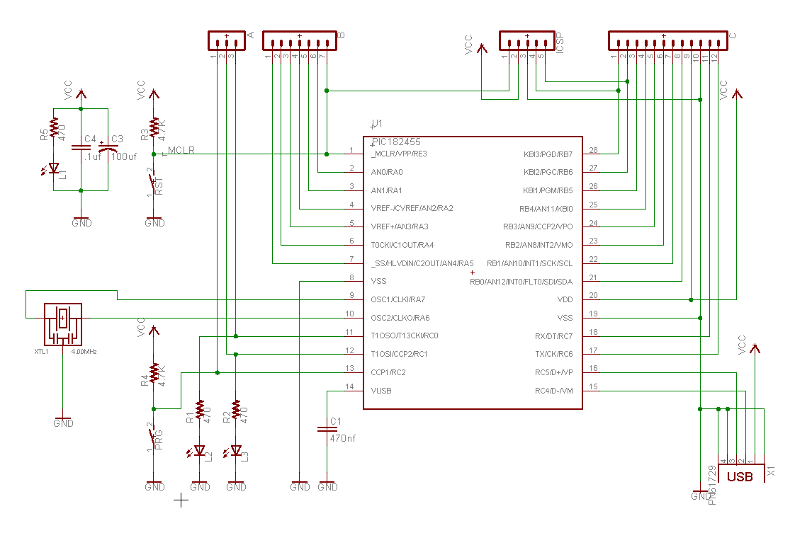
Schmatic:
Same as all other 28 pin versions-

Board Layout:

Guide:

All Files:
Eagle Board File
Eagle Schematic File
Eagle Library File
Bill Of Materials (Excel spreadsheet)
ZIP File containing all of the above
Questions? Just e-mail "brian_schmalz (at) yahoo (dot) com" (edit
address to remove spam foiling changes)


