Description:
So from version 3 to version 4, I only made a couple of changes. The
board got narrower by .100", I moved some components around so that the
LEDs could be in a row and there weren't any resistors that need to
stick straight up (all now lay flat).
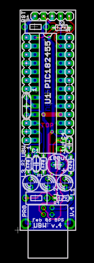
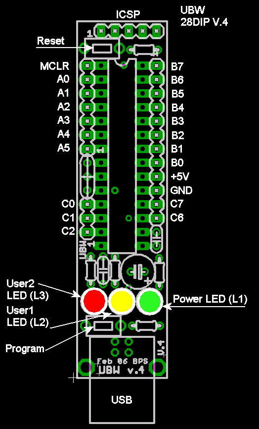
HOWEVER, there is one major error on this board. If you look at the
picture, you'll see that the programming switch is burried between the
USB connector and the LEDs. This means it's impossible to press the
programming button with a finger. Big oops. This problem was corrected
in version 5.
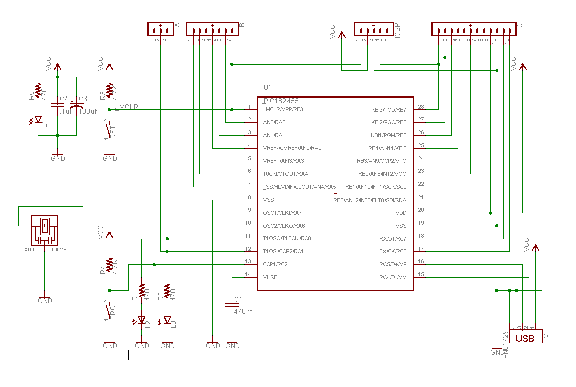
Schmatic:
Same as all other 28 pin versions-

Board Layout:

Guide:

All Files:
Eagle Board File
Eagle Schematic File
Eagle Library File
Bill Of Materials (Excel spreadsheet)
ZIP File containing all of the above
Questions? Just e-mail "brian_schmalz (at) yahoo (dot) com" (edit
address to remove spam foiling changes)


