UBW Tutorial #1: Simple digital input and
output
Summary:
A very simple introduction to using a terminal emulator and a simple
BASIC application to cause some digital outputs to change state based
upon the state of digital inputs.
Theory and Commands Used:
In this tutorial, we will use two push buttons for inputs and two LEDs
for outputs. We will watch the inputs and display output patterns on
the
LEDs based upon what the inputs are. This may seem really, really
basic, but the concepts you learn in this tutorial will be the
foundation of all other UBW work, so it makes sense to start simply.
Please reference the documentation for the firmware you have on your
UBW.
The current version (as of 10-16-07) is for Firmware
D 1.4.2.
We will use the "V" command to see that our UBW is operating properly
and to find out what version it is.
We will use the "C" command to configure the digital inputs and outputs.
We will use the "I" command to read the digital inputs.
We will use the "O" command to output digital outputs.
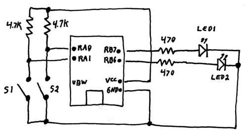
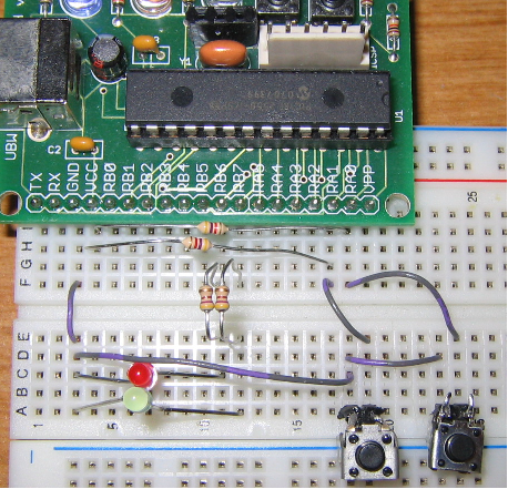
Circuit Setup:
We will have our two switches connecting to Port A bits 0 and 1, and
out LEDs will connect to Port B bits 7 and 8. These bits are completely
arbitrary, you could certainly use any of the other I/O pins on the
UBW, as there are lots of them. I took one of the UBW kits that
spark fun
sells, put male headers into the holes pointing down, and plugged it
into a breadboard for this tutorial. You can do it however you want -
my way is definitely not the only way to get this to work. Note that we
use 470 Ohm current limiting resistors with the LEDs (so they don't
burn out) and 4.7K Ohm pullup resistors on the switches so that the
Port
A inputs pins are either getting +5V (through the pullup resistor) or
are shorted to Ground through the switch.
Using a Terminal Emulator:
You can use the Hyperterminal terminal emulator that came with
Windows, or a different one (I use TeraTerm Pro Web). No matter
which one you use, make sure to turn OFF any hardware handshaking when
you open up the port.
After connecting your UBW, and wiring up the circuit shown above, you
need to find out which COM port your UBW has connected on. Go into the
Windows Device Manager, and look under Ports (COM & LPT) to find
out which COM port your UBW is on. If all of your ports say
"Communications Port (COMx)" and you don't know which one is the UBW,
then double click on each port and look for the one that says
"Manufacturer: Microchip Technologies Inc.". Let's say it is on COM4.
We'll use
that for this tutorial, but substitute whatever value yours is on.
Use your terminal emulator to open a connection to COM4, with no
hardware handshaking. The baud rate and parity and start/stop bits make
no difference (the UBW software completely ignores those parameters -
see the UBW FAQ for more information).
Test out your UBW connection by typing a capitol V and pressing Enter.
You should get a response that looks something like :
UBW FW D Version 1.4.2
The "V" command stands for "Version", and it just asks the UBW to send
back some standard information. It tells you what firmware version it
is, and lets you know that it can receive your commands, and that you
can receive its replies.
(Note that what you type will not show up, and backspace does not work
to correct mistakes in typing.)
Now you know that you have a valid connection to your UBW. Next we need
to tell the UBW what our inputs and outputs are. We use the "C" command
for this. Type the following in, and press Enter at the end of the line
to send it to the UBW.
C,3,0,0,0
The UBW should send back
OK
The "C" command stands for "Configure" and it has four parameters (for
a
28 pin UBW). Each parameter is separated by a comma. The first three
parameters are decimal values that represent which bits of each port
you
want to be inputs and which ones you want to be outputs. The first
parameter is for PortA, the second for PortB, and the third for PortC.
If you send a zero for any of these parameters, you are telling the UBW
that you want that port to be all outputs. If you send a 255, you are
saying you want all of the bits of that port to be inputs. Each bit of
the number represents one of the pins in the port. So, for example, if
you wanted to
make Pin0 of PortB an output, Pin1 an input, and Pins3 through 7
outputs, you would use (binary) 0b00000010 (which is 2 in
decimal). You can make each pin
in each of the ports an input or an output. We want to make PortA Pin0
and Pin1 inputs, so we'll send a 3 (decimal) for the PortA paramter,
and then all other pins outputs, so they all get zeros.
For our example here, the C,3,0,0,0 tells the UBW that we want bits 0
and 1 of PortA to be inputs, and everything else to be outputs. The
last parameter is the number of analog inputs to turn on. We don't want
any, so we leave that zero.
Now we need to read the inputs. We use the "I" command. Type in
I
and press Enter. It will send back a response that looks something like
this :
I,003,000,001
The "I" command stands for "Input" and it has three parameters (for a
28-pin UBW), each separated by a comma. The parameters are
decimal values that represent which bits of each input port are high,
or +5V. The first parameter is for PortA, the second for PortB,
and the third for PortC. Again, each bit of each number represents
the status of one pin on that port. So in the above response,
we can see that my PortA Pin0 has +5V on it, which means the switch is
not closed. PortA Pin1
switch was also +5V, meaning not closed. If you keep typing "I" over
and over again, as you
press and release each switch, you can see the bits representing their
states change. You will get a 000, 001, 002 or 003 for the first
parameter of the I response from the UBW, which is telling you the
state of the two switch on PortA Pin0 and Pin1.
Note that the paramters that the UBW sends back to you on the PC are
always padded with zeros. This is to make the processing of those
messages very easy. You know that, for an "I" command responce, the 5th
charater from the front of the string will _always_ be the ones digit
of the PortA digital input parameter. If the numbers were not zero
padded, then their positions in the string would change as their values
changed.
So, you may have been wondering why there is a 001 in the PortC digital
input parameter above. The reason is because the UBW was outputing a
HIGH (1) on PortC Pin0 at the time that I sent the "I" command. Can you
figure out (from the UBW schematic) why this would be? I'll give you
a hint : it will 'blink' on and off.
Now for lighting up those LEDs. Lets say you wait for both switch
inputs to be HIGH (i.e. +5V) and then you want to light both LED, but
all the rest of the time you want both LEDs to be dark. You use the "O"
command, which takes 3 parameters, again, one for each port.
O,0,0,0
This command will set all of PortB (all of the pins) low, or to Ground.
This turns off the LEDs. Now if we send this command:
O,0,192,0
It will turn on bit7 and bit6 of PortB, which will output +5V at PortB
Pin7 and Pin6, which will turn on both of our LEDs.
By using the I and O commands, you can read any inputs and set any
outputs to either high or low states.
Simple Liberty Basic Example:
The real power of all of this does not lie in using a terminal
emulator. What a lot of typing just for two silly LEDs! But we needed
to learn what to do. Now, we can have some real fun. The power of the
UBW comes from the fact that the PC can read the values of the inputs
and write to the outputs, all under your program's control. What? You
don't have a program? Cool. We'll make one right here.
Download and install Liberty
Basic.Type in the following program (or copy/paste), but be careful
to change the
"COM4" part to whatever COM port your UBW is on. This program will
configure the UBW, then continuously read the inputs and set the LED
outputs automatically based upon the inputs it sees. It will loop
through 100 times and then stop.
' UBW Tutorial #1 Liberty Basic application code
' Written by Brian Schmalz on 10/16/2007, for UBW FW D 1.4.2
' First open the COM port to the UBW
OPEN "COM4:9600,N,8,1" for random as #UBW
' Then send the C command with the proper parameters
PRINT #UBW, "C,3,0,0,0"
' Then go in a loop, sending I commands, waiting for a response, and deciding
' what to do based upon that response.
FOR x = 1 to 100
' Wait a bit for UBW to respond
FOR T = 1 to 10000
NEXT T
' Then read in any response from UBW and discard
Nothing$ = INPUT$(#UBW, LOF(#UBW))
' Send the "I" command
PRINT #UBW, "I"
' And wait for 14 characters to come back
WHILE LOF(#UBW) < 14
WEND
' Read in the data
InData$ = INPUT$(#UBW, LOF(#UBW))
' Now make our decision
IF MID$(InData$, 5, 1) = "0" THEN
' If both switches are PRESSED, then turn the LEDs ON
PRINT "Turning LEDs ON"
PRINT #UBW, "O,0,192,0"
ELSE
' If both switches are not PRESSED, then turn the LEDs OFF
PRINT "Turning LEDs OFF"
PRINT #UBW, "O,0,0,0"
END IF
NEXT x
CLOSE #UBW
PRINT "All done."
END
So there you are. You now have a very configurable AND gate. The LEDs
only turn on if both switches are pressed down. That's an AND gate!
Taking Things Further:
Now you know the basics. There are many more interesting commands to
learn, but with just the information contained in this tutorial, you
could easily make 8 LEDs blink in any pattern you like, you could use
your two switches to 'click' in a pattern, store it in your
application, the play it back on your LEDs, you could make the buttons
cause a light pattern on the LEDs, etc. And that's just with switches
and LEDs - you can (using various circuits, all of which can be found
on the web in different places) connect your UBW up to infrared
detectors to time slot car or pine wood derby races, you could connect
your UBW up to your Christmas lights to make different patterns, etc.
etc.
Questions? E-mail me at